

by: Leonardo Corbucci 16 Ottobre 2024 13:28
How is the performance of a photovoltaic system calculated?
In this new in-depth analysis, we will explore a highly relevant topic: the standard procedure for evaluating the performance of a photovoltaic system, providing and offering reference images with specifications of the tests performed.
The Monitoring and Testing of Performance.
Today, more than ever, the rapid deployment of photovoltaic systems must be supported by appropriate activities such as:
- Verification
- Monitoring
- Performance testing
This is essential to ensure the correct energy production (MWh) and safeguard the project’s financial outcomes.
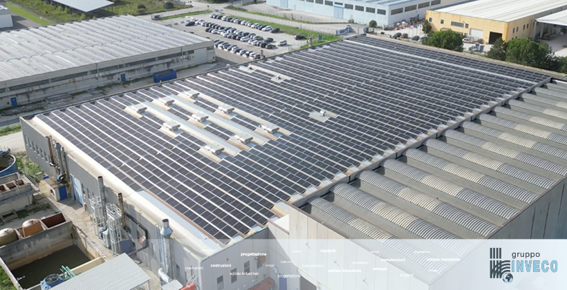
We can already state that a proper assessment of the functionality and performance of a photovoltaic system, whether newly installed or existing, cannot disregard the following activities:
- Verification of the electrical continuity and connections between photovoltaic modules
- Verification of the insulation resistance of electrical circuits from the grounding, ensuring compliance with the values set by CEI 64-8 Standard
- Functional testing of the static conversion system, referring to the user and maintenance manual under different power conditions (start-up, shutdown, loss of grid connection)
- Performance verification on the DC side
- Performance verification on the AC side (inverter)
- Thermal imaging analysis
- Visual inspection
- Additional performance checks on the DC side.
For each of the mentioned activities, there is a sequence of operational phases that must always be followed. This is to ensure proper energy production (MWh) and safeguard the project’s economics.
Electrical Continuity Check (PV Modules)
In this section of the in-depth analysis, we will thoroughly explore the individual operational phases of the process, focusing on how each one contributes to the final result.
A key element will be the use of a voltmeter, an essential measuring tool for monitoring and verifying the correct functioning of the electrical system, ensuring precision and reliability at every step.
Phase 1: Ensure that the inverter is turned off and set the field and string isolators to the OFF position.
Phase 2: Using a voltmeter, measure the open-circuit voltages of the strings. The voltages should be similar; a maximum deviation of 10% between values is acceptable. If the measured values differ from the module’s nameplate data, calculate the reduction in open-circuit voltage, using approximately 2.3 mV/°C for each crystalline silicon cell connected in series.
Note: An increase in temperature corresponds to a decrease in open-circuit voltage of about 2.3 mV/°C and an increase in short-circuit current of approximately 0.2%.
Phase 3: If no values are obtained during the measurement, it indicates a disconnection in the module series. In this case, the termination boxes and cable lugs should be checked.
Phase 4: If the open-circuit voltage measurement shows values that differ beyond the acceptable deviation percentage, this suggests the presence of either a defective module, reversed bypass diodes, or reversed polarity in one or more modules.

Measurement of electrical circuit insulation from ground.
Insulation measurement is a crucial step to ensure the safety and efficiency of electrical systems and equipment.
By using a 1kV insulation tester, we can assess the resistance of the insulating material, identifying any critical issues that could compromise the system’s operation.
Now, let’s take a closer look at the individual steps of the insulation measurement process with the respective instrument.
Step 1: Ensure the inverter is switched off and set the field and string isolators to the OFF position.
Step 2: Connect the negative lead of the insulation tester to the ground.
Step 3: Connect the positive lead of the insulation tester to the positive terminal of the string.
Step 4: Apply a voltage of 1kV and read the resistance value, which should be in the range of hundreds of MΩ.
Step 5: Repeat steps 2 and 3 (this time connecting the positive lead of the tester to the negative terminal of the string) and then perform step 4.
Step 6: If the resistance readings are in the range of hundreds of KΩ instead of hundreds of MΩ, it indicates a fault in the modules.
Generated Power Conditions & Conversion Unit
At this stage, the proper functioning of the photovoltaic system is verified under different power generation conditions and in the various modes provided by the conversion unit.
Step 1: Keep the grid interface switch in the OFF position and switch ON the field and string disconnectors.
Step 2: The inverter will detect the photovoltaic array, power up, and begin searching for the electrical grid.
Step 3: Switch ON the grid interface switch.
Step 4: The inverter will start monitoring the grid voltage and frequency, and will initiate operation if these parameters fall within the prescribed tolerances.
Step 5: After a stabilization period, the inverter will begin tracking the Maximum Power Point (MPPT).
Step 6: Verify the inverter shutdown in the event of a grid outage (in compliance with current regulations, the inverter must shut down in the absence of a grid). This can be simulated by switching OFF the grid interface switch.
Step 7: Verify the automatic restart of the inverter when the grid returns.
Performance Condition Assessment.
Now, we will explore the key parameters that affect the efficiency and performance of the system, evaluating the optimal operating conditions to ensure maximum energy production.
Below, we present the performance condition on the direct current side:

Regulation Compliance for Photovoltaic System Testing Certification
The regulation stipulates that the aforementioned condition must be met in order to issue the certification for the testing of a photovoltaic system.
- Pcc: Power (kW) measured at the output of the photovoltaic generator, with an accuracy better than 2%.
- Pnom: Total rated power (kW) of the installed modules.
- I: Irradiance (W/m²) measured on the module plane, with an accuracy better than 3%.
- ISTC: Standard Test Condition irradiance, with a reference value of 1000 W/m².
- Pca: Active power (kW) measured at the converter output, with an accuracy better than 2%. Measurement instruments used: Pyranometer, Millivoltmeter, Clamp Meter, and/or Wattmeter.
Measurement Procedure to be Followed in Each Step:
Step 1:
Start the inverter and wait for its operation to stabilize.
Step 2:
Place the pyranometer on the module plane and measure the solar radiation, which is obtained by dividing the millivoltmeter reading by the pyranometer’s calibration constant.
Solar Radiation [W/m²] = Millivoltmeter [mV] ÷ Calibration Constant [mV/W/cm²]
Step 3:
After demagnetizing the clamp meter, position yourself under the field disconnector and attach the clamp to the positive cable of the PV field.
Also, record the voltage and perform the DC power measurement.
Step 4:
Verify that the test condition is met.
Step 5:
If the condition is not met, this indicates DC-side losses exceeding 15%.

Comparison: Verification of the Performance Condition on the AC Side (Inverter)
Regulations require that the aforementioned DC/AC conversion condition must be met in order to issue the photovoltaic system’s commissioning certificate.
- Pcc: Power (kW) measured at the output of the photovoltaic generator, with an accuracy better than 2%.
- Pca: Active power (kW) measured at the output of the converter with an accuracy better than 2%. Measurement instruments to be used: Clamp meter and/or wattmeter.
Measurement Procedure:
Step 1:
Start the inverter and wait for its operation to stabilize.
Step 2:
After demagnetizing the clamp meter, position it under the field disconnector and attach the clamp to the positive cable of the PV array.
Also, measure the voltage and record the DC power measurement.
Step 3:
Position yourself under the interface switch and attach the clamp to the phase cable.
Also, measure the voltage and record the AC power measurement.
It is preferable to perform steps 2 and 3 using two clamp meters, so that measurements can be taken simultaneously.
Step 4:
Verify if the commissioning condition is met.
Step 5:
If the condition is not met, it means the inverter has an efficiency of less than 90%, and is therefore non-compliant.
Thermal Camera: Photovoltaic Module Performance Assessment
We would also like to share with you some images captured using a thermal camera that highlight the condition of the cells in a newly installed photovoltaic system.
As can be observed from the images, the temperature of the cells is completely uniform, with no asymmetries detected between them (a situation that typically occurs in the case of “hot spots,” where individual cells are damaged).
The only temperature differences found on the surface of the modules are solely due to the varying exposure of the photovoltaic modules to sunlight.
Therefore, using a thermal camera is an essential procedure for assessing the proper performance of:
- Cells
- Modules
- The entire PV system.

Various cases of module evaluation using a thermal camera.
Based on the following images captured with a thermal camera, the issue of module cells generating heat due to dirt buildup is highlighted, behaving as actual “hot spots” and thus compromising the performance of both the module and the string.
After performing an adequate cleaning of the photovoltaic modules, the cell temperatures can return to normal.
This demonstrates that the issue was not related to a defect in the module, but rather was exclusively due to dirt accumulation.
It is therefore advisable to consider seasonal cleaning for all photovoltaic modules exposed to dirt.
Individual performance assessments of a PV system.
After reviewing the declaration of conformity pursuant to Law 46/90, issued by the installer, the following verifications are necessary:
- Ensuring that the system complies with the design, the modules are correctly installed, and the structure is securely anchored.
- Verifying that the system has been built in accordance with general standards and the relevant specific standards.
- Confirming that the electrical materials comply with the applicable standards and that no visible damage is present that could compromise safety.
- Ensuring the installation of appropriate disconnection and interruption devices.
Additionally, the following should also be considered:
- Inspection of cables and conductors.
- Verification of grounding for masses and surge protectors.
- Functional tests on the static conversion system, with reference to the operation and maintenance manual, under various power conditions:
- Power-on
- Power-off
- Loss of network connection.
Details and Insights: CC Performance
Further assessments are necessary to evaluate the impact of thermal losses on the direct current output of the PV system.
Under the same atmospheric conditions, not all PV systems are equally affected by thermal influences.
For instance, ground-mounted systems or those installed with “sail” type structures are better ventilated and less prone to thermal rise.
On the other hand, rooftop systems (typically installed in recent years in a flush configuration with the roof surface) suffer from poor natural ventilation, leading to a significant increase in cell temperatures, which negatively affects the performance of both the photovoltaic modules and the system as a whole.
Conclusion.
Calculating the performance of a photovoltaic system is a process that requires consideration of several factors.
Understanding these parameters not only allows for monitoring the energy yield of the system but also enables the optimization of its operation and maximization of the return on investment.
Investing in constant monitoring and data analysis ensures the ability to intervene promptly, guaranteeing greater economic and environmental sustainability over time.
Ultimately, understanding how to calculate the performance of a photovoltaic system is an essential tool for informed and efficient energy management.
Insight by Eng. Andrea Girelli – Energy Management & Renewables.
Recent Posts
Categories
